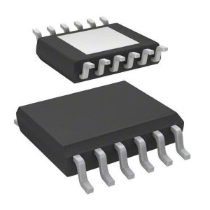
SPC5644AF0MLU2 32-bit Microcontrollers – MCU 32BIT3MB Flsh192KRAM
♠ Product Description
| Product Attribute | Attribute Value |
| Manufacturer: | NXP |
| Product Category: | 32-bit Microcontrollers - MCU |
| RoHS: | Details |
| Series: | MPC5644A |
| Mounting Style: | SMD/SMT |
| Core: | e200z4 |
| Program Memory Size: | 4 MB |
| Data RAM Size: | 192 kB |
| Data Bus Width: | 32 bit |
| Maximum Clock Frequency: | 120 MHz |
| Minimum Operating Temperature: | - 40 C |
| Maximum Operating Temperature: | + 125 C |
| Qualification: | AEC-Q100 |
| Packaging: | Tray |
| Brand: | NXP Semiconductors |
| Moisture Sensitive: | Yes |
| Processor Series: | MPC5644A |
| Product Type: | 32-bit Microcontrollers - MCU |
| Factory Pack Quantity: | 200 |
| Subcategory: | Microcontrollers - MCU |
| Part # Aliases: | 935321662557 |
| Unit Weight: | 1.868 g |
♠ 32-bit Microcontrollers - MCU
The microcontroller’s e200z4 host processor core is built on Power Architecture® technology and designed specifically for embedded applications. In addition to the Power Architecture technology, this core supports instructions for digital signal processing (DSP). The MPC5644A has two levels of memory hierarchy consisting of 8 KB of instruction cache, backed by 192 KB on-chip SRAM and 4 MB of internal flash memory.
The MPC5644A includes an external bus interface, and also a calibration bus that is only accessible when using the Freescale VertiCal Calibration System. This document describes the features of the MPC5644A and highlights important electrical and physical characteristics of the device.
• 150 MHz e200z4 Power Architecture core
— Variable length instruction encoding (VLE)
— Superscalar architecture with 2 execution units
— Up to 2 integer or floating point instructions per cycle
— Up to 4 multiply and accumulate operations per cycle
• Memory organization
— 4 MB on-chip flash memory with ECC and Read While Write (RWW)
— 192 KB on-chip SRAM with standby functionality (32 KB) and ECC
— 8 KB instruction cache (with line locking), configurable as 2- or 4-way
— 14 + 3 KB eTPU code and data RAM
— 5 ✖ 4 crossbar switch (XBAR)
— 24-entry MMU
— External Bus Interface (EBI) with slave and master port
• Fail Safe Protection
— 16-entry Memory Protection Unit (MPU)
— CRC unit with 3 sub-modules
— Junction temperature sensor
• Interrupts
— Configurable interrupt controller (with NMI)
— 64-channel DMA
• Serial channels
— 3 ✖ eSCI
— 3 ✖ DSPI (2 of which support downstream Micro Second Channel [MSC])
— 3 ✖ FlexCAN with 64 messages each
— 1 ✖ FlexRay module (V2.1) up to 10 Mbit/s with dual or single channel and 128 message objects and ECC
• 1 ✖ eMIOS: 24 unified channels
• 1 ✖ eTPU2 (second generation eTPU)
— 32 standard channels
— 1 ✖ reaction module (6 channels with three outputs per channel)
• 2 enhanced queued analog-to-digital converters (eQADCs)
— Forty 12-bit input channels (multiplexed on 2 ADCs); expandable to 56 channels with external multiplexers
— 6 command queues
— Trigger and DMA support
— 688 ns minimum conversion time
• On-chip CAN/SCI/FlexRay Bootstrap loader with Boot Assist Module (BAM)
• Nexus
— Class 3+ for the e200z4 core
— Class 1 for the eTPU
• JTAG (5-pin)
• Development Trigger Semaphore (DTS)
— Register of semaphores (32-bits) and an identification register
— Used as part of a triggered data acquisition protocol
— EVTO pin is used to communicate to the external tool
• Clock generation
— On-chip 4–40 MHz main oscillator
— On-chip FMPLL (frequency-modulated phase-locked loop)
• Up to 120 general purpose I/O lines
— Individually programmable as input, output or special function
— Programmable threshold (hysteresis)
• Power reduction mode: slow, stop and stand-by modes
• Flexible supply scheme
— 5 V single supply with external ballast
— Multiple external supply: 5 V, 3.3 V and 1.2 V
• Packages
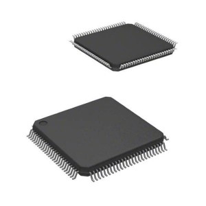
— 176 LQFP
— 208 MAPBGA
— 324 TEPBGA
496-pin CSP (calibration tool only)


